UrbiCAD Self-Protection Plans

Self-Protection Plans: Emergency Plans for Fire and Evacuation Plans for Buildings and Offices

The various programs permit:

  • The design of the Self-Protection Plans for buildings, industrial facilities, commercial offices or any other installations: The system allows Self-Protection Plans to be documented and formalized for the development of Emergency Plans for fire or other risks including evacuation plans for buildings and offices.
  • Plan creation: Using the CAD tools, maps and diagrams can be created, automating design processes, locations, signage, meeting points, evacuation routes, itineraries, protection equipment and symbols, location of equipment, accessibility, enclosure of action zones, establish fire load criteria, integrity and thermal insulation of elements and structures, etc.

Self-Protection Plans: Emergency Plans for Fire and Evacuation Plans for Buildings and Offices

More information

Click the image buttons for more information

Self-Protection Plans: Emergency Plans for Fire and Evacuation Plans for Buildings and Offices

The organisation of the different chapters of the Self-Protection Plan for facilities or installations of any kind are based on the following:

A) The risks inherent in the activity (fire, explosion, spills, radiation, gas leaks, etc).

B) The risks which are a consequence of the activities (armed attack, robbery, bomb warning, hostage taking, sabotage, etc).

C) General risks as indicated in the Civil Protection Plans (floods, snowstorms, earthquakes, volcano eruption, etc).

The document is structured into the following Chapters:

  • Chapter 1º: Identification of titles.
  • Chapter 2º: Detailed description of the activity and facilities.
  • Chapter 3º: Inventory, analysis and evaluation of risk.
  • Chapter 4º: Inventory and description of Safety and Security measures and equipment.
  • Chapter 5º: Maintenance program for installations.
  • Chapter 6º: Emergency Plan.
  • Chapter 7º: Integration of the Self-Protection Plans into other processes.
  • Chapter 8º: Implementation of the Self-Protection Plans.
  • Chapter 9º: Maintenance and Updating of the Self-Protection Plan.

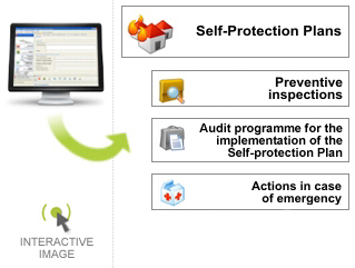
The application also permits the development of further actions based on the Self-Protection Plan, including:

  • Perform Safety Inspections, both for fire prevention installations (fire stations, sprinklers, fire detectors, extinguishers, etc.) and the operating facilities themselves (storage tanks, gas lines, electrical installations, transformers, etc).
  • Auditing of the implementation of the Self-Protection Plans, and the corresponding reports.
  • Manage alarms and Emergency situation communication as well as the Action Protocols in the case of emergencies (an application which can be installed in all equipment necessary).

By using the different features of the application, measures for the formalisation of the Self-Protection Plans can be created and programmed easily and intuitively. The application captures the initial data which can be modified using an explorer in order to control and manage any chapter of the Self-Protection Plans.

  • The CAD maps required for the Self-Protection Plans can be included and form part of the final document and may also include images, graphs, tables, etc.
  • Different Action Diagrams can also be included in the Self-Protection Plans. These diagrams are designed using a Diagram Editor incorporated into the application, allowing any action to be mapped or existing maps to be altered using the default diagram setting.
  • Finally, the application permits (through Gantt diagrams) different actions to be planned such as actions, meetings, information sessions, training activities, etc.

The documents obtained using the different programs of the application are completely flexible, with clear, accurate and reliable content and, most importantly, "constantly adapted to meet changing norms or recommendations from Civil Protection authorities".

All documents can be previewed before printing from where they can be printed directly or stored in various formats: Microsoft Word .DOC, Adobe .PDF, or in .HTML, format, including, of course, all types of images, AutoCAD plans or from other CAD platforms and photographs.

CAD Application for the development of the Emergency and Evacuation Maps.

The application offers a series of tools which permit the creation of the various maps of an Emergency Plan for different CAD platforms, for the creation of required maps, automating design processes, locations, signage, sectorisation, meeting points, evacuation, designation of itineraries, signs for installations, location of equipment, access, delimitation of action areas, etc.

  • Facility map
  • Location map
  • Building floor plan
  • Risers and/or facades
  • Meeting points
  • Evacuation pictograms

The CAD application is available for the following platforms:

CAD SOFTWARE VERSION COMMENTS
AutoCAD/ Architectural Desktop/ AutoCAD Map Version 2000 to 2022 100% Operative
AutoCAD LT Version 2000 to 2022 Works under AutoCAD LT limitations
4mCAD Version 2000 to 2022 100% Operative
BricsCAD Version 2000 to 2022 100% Operative
ZwCAD Version 2000 to 2022 100% Operative
GstarCAD Version 2000 to 2022 100% Operative

(*) For Professionals, Companies and/or Prevention Services without an installed CAD platform OEM version will be provided. Contact UrbiCAD for more information.

Working with the CAD application

When working with the CAD application, we can directly access the Project Assistant or navigate through the various options of the application which allows the creation of maps and plans.

If we access the Project Assistant it will present a proposal for the maps required for the Emergency Plan according to the Facility Use.

Different maps can be created by navigating through the various tools of the application:

  • Installation Symbols: Both for normal symbols and pictorial symbols which are more appropriate for certain spaces and uses.
  • Signage: For various elements, locations, rooms, workshops, warehouses, machine rooms, meters, etc. It also allows the installation of signs for First Aid equipment, Emergency equipment, Fire extinguishing equipment, etc.
  • Special emergency lighting: Properly indicating emergency lighting systems.
  • Sectorisation: Delimitation of spaces by sectors, each graphically represented
  • Identification of spaces: Establishing the identification of different locations, rooms, warehouses, etc.

Project Assistant

  • Risk and Safety signage: Identifying locations of risk due to stored materials, or activities carried out as well as Electrical Panels and High Risk Installations.
  • Technical and safety equipment: Distribution of technical and safety equipment in the various spaces and locations.
  • Occupancy by floor: Establish the occupancy by location, floor and building.
  • Evacuation means: Doors, hallways, vestibules, accesses, stairs, ramps, garages, sectors, etc.
  • Evacuation routes: Permits the designation of itineraries, evacuation routes, delimitation of action areas, location of emergency equipment, access, colour coding of areas and sectors, etc.
  • Fire resistance: Establish the minimum fire resistance for structural elements in reinforced concrete, metal and mixed structures.
  • Reaction to fire: Graphically represent the conditions for fire reactivity and resistance (Load capacity R, Integrity E and thermal insulation I), of construction elements according to applicable classifications.
  • Graphics: Various uses for graphic representation to identify areas of special risk, alarms in various languages, areas representing a risk of fire, explosion, etc. Includes symbols used for the representation of various installations (electrical, telecommunications, gas, plumbing, etc).
  • Details: Includes the various related details, appropriately structured, which can be implemented into plans and offering the user the ability to incorporate their own details into the application easily.

One important aspect is that the various plans created can be implemented in any of the different items of the documents executed from the software application, such as the Urban Emergency Plans, Self-Protection Plans or the Auditing and Installations Reports.

Connectivity between documents and the CAD application

The completed documents generated by the application can be consulted using the CAD Application, allowing the design values and habitability data from these documents to be incorporated into the plans.

The design values and habitability data obtained through the Management Program can be read using the CAD application.

View a DEMO

View a Demo

Multimedia content  |  Use of software  |  Interactive

On-line Software demo

Trial use of UrbiCAD software

Multimedia Content  |  Use of Software  |  Interactive  |  Only Office hours

Our advice

We strongly believe that the best way to know our software is trying it. So we provide to you our free demo on-line service.

How can I purchase UrbiCAD products?

Contact with UrbiCAD architecture SL

You can combine payment methods to pay for your purchase. Choose from the following combinations:

  1. Bank Transfer.
    If you want to pay for your purchase using a bank Transfer, contact UrbiCAD in order to obtain the current account number.
  2. Credit Card.
    To pay for your purchase using a Credit card through gateway payment. Using the order form of the product platform (UrbiCAD will send the link).

What information is necessary to order a product?

  1. Invoice data: Name, Postal address, Fiscal ID#.
  2. Shipping address if not the same as billing address.
  3. Licence Nº if you are a user and wish to request a program update.
  4. Product platform and platform version. As well as language preference (English / Spanish)

How will I receive the product?

"With prior payment through Bank Transfer or Credit Card":

You can download the software from a link that UrbiCAD will send you. You can work with the software from download and once you activate your license by the Internet.

For further information, please visit FAQs.